Use connections
You can create connections and set up their appearance.
If Smart Modeling is enabled, you can use the  Insert icons to link placed objects.
Select the object you want to connect with an object that has already been placed. The
Insert icons are displayed.Click the
Insert icon on the side of the selected object to which you want to attach the connection and hold down the mouse button.Move the mouse pointer to the border of the target object.
Release the mouse button at the connection anchor point where you want to connect the target object. If you can create more than one connection between the objects, the selectable connections are displayed and the currently used connection is highlighted in bold.
If you want to use another connection, click the corresponding name, otherwise click the modeling area. The connection selection is closed.
You have created a connection using the Insert icon of Smart Modeling.
If Smart Modeling is enabled, you can use the Smart Modeling toolbar to link placed objects.
Select the object you want to connect with an object that has already been placed. The
Insert icons are displayed.Click the
Insert icon on the side of the selected object to which you want to attach the connection. The Smart Modeling toolbar opens.In the Smart Modeling toolbar, click
 Connection.
Move the mouse pointer to the border of the target object.
Release the mouse button at the connection anchor point where you want to connect the target object. If you can create more than one connection between the objects, the selectable connections are displayed and the currently used connection is highlighted in bold.
If you want to use another connection, click the corresponding name, otherwise click the modeling area. The connection selection is closed.
You have created a connection using the Smart Modeling toolbar.
You can use the mini toolbar to link objects.
Prerequisites
The mini toolbar is only available if Smart Modeling is disabled.
Click the placed object symbol. The mini toolbar is shown.
In the mini toolbar, click the symbol you want to place in the modeling area.
The Select connection box and the outline of the object are displayed. The currently used connection is marked with a preceding bar and is highlighted in bold.
Click another connection or close the Select connection box with
 Close.
Move the mouse pointer to the modeling area. The frame of the object is displayed. If Guided modeling is enabled, lines indicate the alignment of the moving object to the placed objects and arrows indicate the distances.
Click the position in the modeling area where you want to insert the object symbol. The name of the object symbol is selected for overwriting by default.
If necessary, overwrite the previous name with the name of your choice and press Enter.
The object symbol is placed in the modeling area and linked to the previously selected object symbol using the selected connection.
You can link placed objects by using the Symbols bar.
In the
 Symbols bar click
  Create connection.
Click the object you want to connect with another object.
Click a target object that can be connected to the source object. If the method does not allow objects to be connected to one another, a prohibitory sign is displayed on the target object; the connection cannot be attached to this object.
Both objects are linked by a connection.
You can link placed objects by using the mini toolbar.
Prerequisites
The mini toolbar is only available if Smart Modeling is disabled.
In the modeling area, click the object you want to connect with another object. The mini toolbar is shown.
In the mini toolbar, click
Create connection.Click a target object that can be connected to the source object. If the method does not allow objects to be connected to one another, a prohibitory sign is displayed on the target object; the connection cannot be attached to this object.
Both objects are linked by a connection.
You can connect already connected objects with a new connection or with an existing connection of the same type if allowed by the method. For example, more than one connection of type has flow two is allowed between two objects of the Organizational unit type.
Create a connection between two objects that are already connected and for which more than one connection of the same type is allowed. The Connect objects dialog opens.
Keep the Create a new connection option enabled if you want to create a new connection with the connection type of the connection with which the objects are already connected.
Enable the Select relationship based on connection role option , click the
 down arrow, and select the connection role of the existing connection to which you want to connect the object. Connections where the Connection role attribute is not specified are listed with (Connection role not specified).
Click Connect objects.
You have connected two objects with more than one connection of the same connection type.
You can change the arrows of the connection to the source and target objects.
Select the connections for which you want to change the arrows.
Click the Start tab bar if not already selected.
Click
 Connection arrows > Towards source. The connection arrows are listed.
Select the connection arrow you want to use in the direction of the source object.
Click
Connection arrows > Towards target.Select the connection arrow you want to use in the direction of the target object.
You have changed the connection arrows to the source and target objects. If you want to use the connection arrow specified by ARIS, select ARIS default instead of a connection arrow.
Select the connections you want to adjust.
Click the Start tab bar if not already selected.
Click
 Line color. The color palette opens.
Click the color you want to apply.
The connection color is adjusted.
Tip
Using the color palette, you can define another color or reset the color to the default color.
Select the connections you want to adjust.
Click the Start tab bar if not already selected.
Click
 Line style.
Click the solid, dashed, or dotted line to adjust the selected connections.
Click
 Line weight.
Click the weight in points in which to display the connections.
The line style and the line weight of the selected connections are adjusted.
Open the model you want to adjust.
Activate the Model tab bar.
Click
 Connection properties. The Edit connections dialog opens.
Click the Bridge height field and specify the height of the bridge. The higher the value, the higher the bridge. A preview of the specified bridge height is displayed.
Click the Rounding intensity field and specify the degree of edge rounding for connections with directional changes. The higher the value, the stronger the rounding. A preview of the specified edge rounding is displayed.
Click OK.
The bridge height and rounding intensity of the current model's connections are adjusted.
You can change the arrows of the connection to the source and target objects.
Select the connections for which you want to change the arrows.
Click the Start tab bar if not already selected.
Click
Connection arrows > Towards source. The connection arrows are listed.Select the connection arrow you want to use in the direction of the source object.
Click
Connection arrows > Towards target.Select the connection arrow you want to use in the direction of the target object.
You have changed the connection arrows to the source and target objects. If you want to use the connection arrow specified by ARIS, select ARIS default instead of a connection arrow.
You can select the object that is linked to the selected object by a connection.
Select the occurrence of the relevant object in the modeling area.
Click
 Details. The Details bar opens.
Click the Relations tab if it is not active yet. The relations of the selected object are listed.
Next to the name of the occurrence of a relationship (connection)
 , click
  More > Go to object.
The connected object is selected in the modeling area.
You can view and select the connection between a source and target object.
Select the occurrence of the relevant object in the modeling area.
Click
Details. The Details bar opens.Click the Relations tab if it is not active yet. The relations of the selected object are listed.
Next to the name of the occurrence of a relationship
(connection), click More > Display connection.
The connection between source and target object is selected. If multiple occurrences of a source object are used in a model, any connections that do not yet exist between the occurrences and the target object are created and selected.
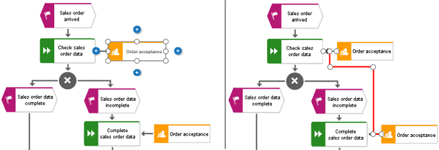
The following graphic shows two occurrences of the Order acceptance object.
If you select one of the object occurrences and enable the Display connection function for the carries out connection, a carries out connection to the second Order acceptance occurrence is also created.
In an open model, you can delete connections that do not have any occurrences in models for specific objects.
Select the occurrence of the relevant object in the modeling area.
Click
Details. The Details bar opens.Click the Relations tab if it is not active yet. The relations of the selected object are listed.
Next to the name of a relationship that has no occurrences in a model
 (connection), click More >
  Delete.
If the connection no longer has any occurrences in any model, it is deleted. If it still has an occurrence in a model, a message is displayed and the connection is not deleted.